Module 2 Activity Research

Weekly Activity

Yiyang Zhang


Project 2


Module 2 — Context-Aware Outfit Advisor

This project builds a context-aware outfit advisor. It reads local weather (temperature, humidity, wind, precipitation) and maps simple rules into daily clothing tips. Output combines a servo pointer gauge and LCD text. We start with fast cardboard prototypes and progress to a sensor + microcontroller build for real-world testing.

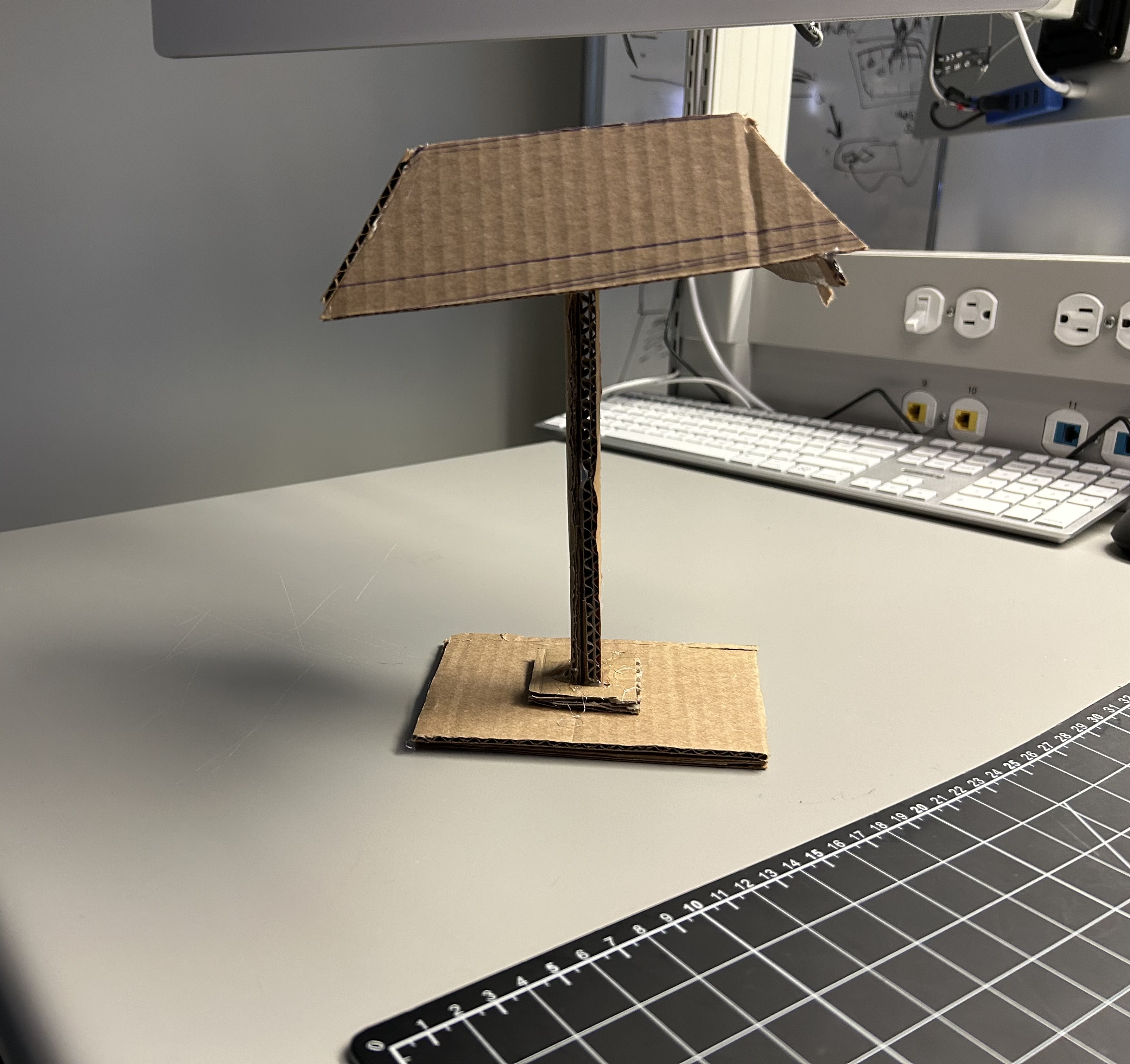
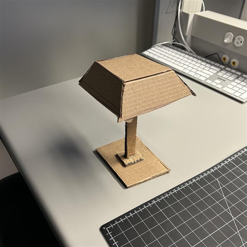
In-Class Activity 1 Geurrilla Prototyping I

Cut parts (start). Base, two ribs, and slot pieces from corrugated cardboard. Measure and layout. Pencil lines set angle and slot depth before cutting. Assembly. Ribs tacked with hot glue; tape used for temporary positioning. Prototype V1. Usable, but angle range and cable clearance are limited. Prototype V2. Wider base and a rear wedge improve stability and add viewing options.

References (video tutorials that informed each step)

  1. Tutorial #1 (basis for Images 1–2): https://www.youtube.com/watch?v=eFnLHOCWO3o
  2. Tutorial #2 (optimizations for Images 3–4): https://www.youtube.com/watch?v=3LgJ7QjEKZs
  3. Tutorial #3 (additional ideas for Image 5): https://www.youtube.com/watch?v=PvNSH1UmjEk

Notes: alt texts describe the action --> problem and benefit --> takeaway.

In-Class Activity 2 — Guerrilla Prototyping II

Step 0 — Reference style :a cartoon lamp icon used to lock rough proportions between shade, post, and base; not a real build photo—only a reference. Step 1 — V1 skeleton: cardboard base + slim post to quickly test center of mass and load. Issue: wobble at the post–base joint; fix: enlarge base or add triangular bracing. Materials: corrugated cardboard, light hot-glue tacks. Step 2 — Shade mock-up: trial shade mounted on the post to simulate real torque. Problem: front tilt lifts the base; tipping risk is high. Decision: add a rear wedge brace or a twin-post layout to share the moment. Step 3 — V2 stability upgrade: larger base and added support on the load side; shade attachment strengthened. Result: lateral sway is reduced and the model stays put during desk use. Next: improve cable routing and fine-angle adjustability. Step 4 — Joinery & cable planning: top view to inspect glue points and cardboard grain; leave channels and tie points for future light/sensor wiring. Hot-glue tacks + tape bridges keep it mod-friendly for revisions.
These are the 5 ideas that we came up with as a group for our brainstorming of the concep This is a table summarize the feedbacks we gathered 3 sketches for narrowing down our ideas rapid prototype of the lamp - top perspective view rapid prototype of the lamp - side perspective view

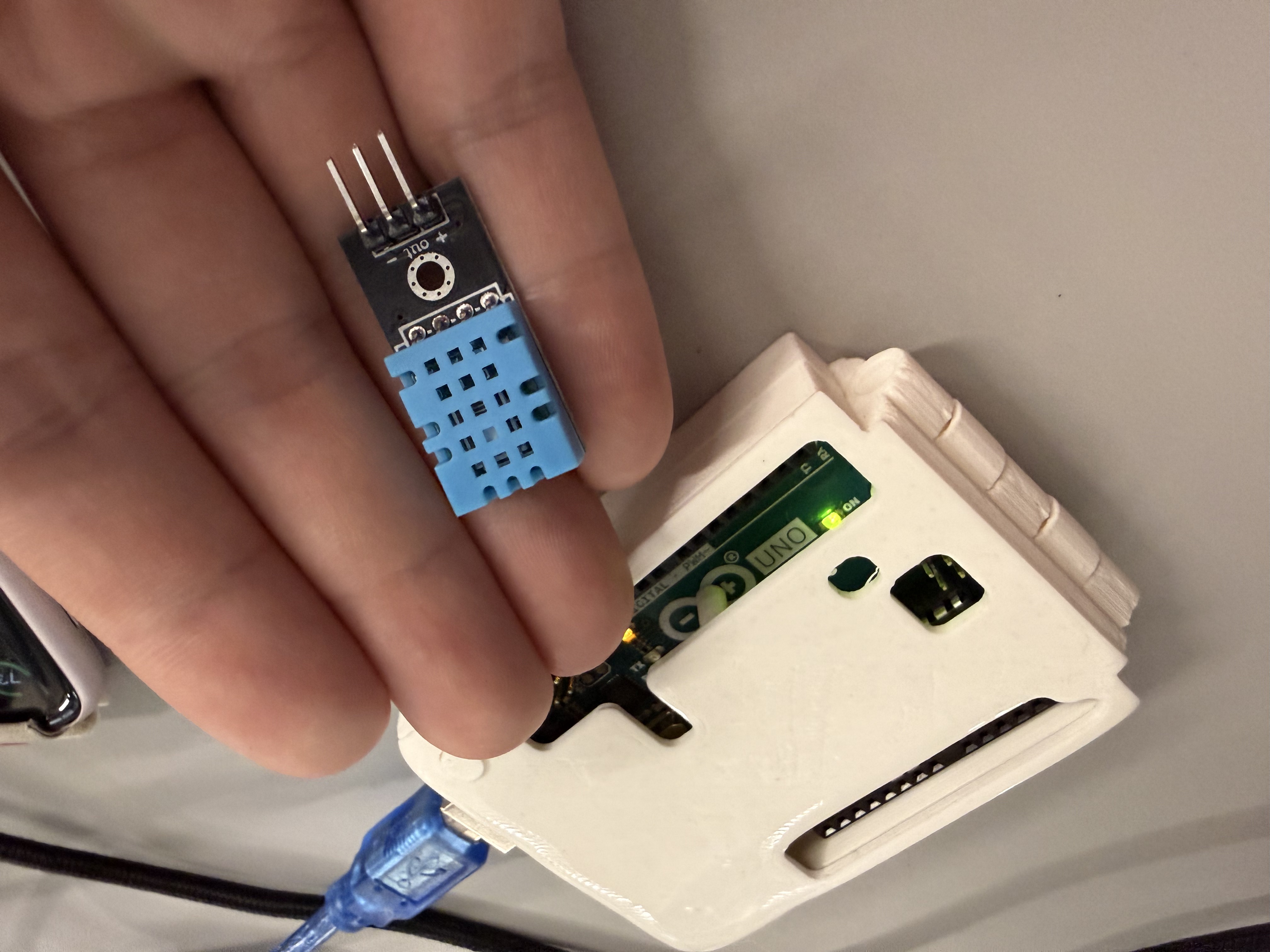
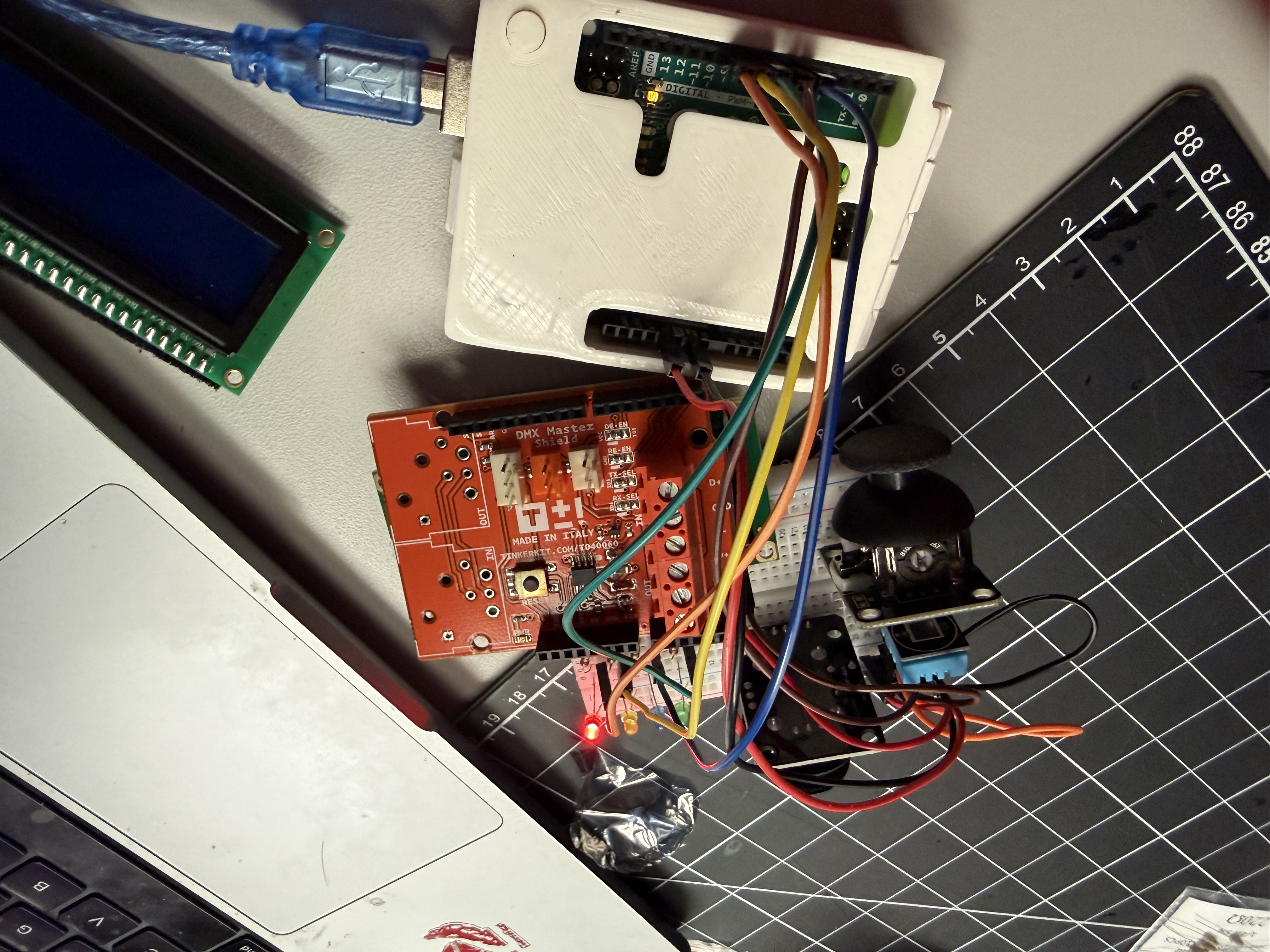
Activity 1 — DHT11 Sensor Exploration & Testing

Step 1 — Cardboard prototype (lampshade form): checks balance, touch stability, and internal volume reserved for future electronics. Step 2 — Arduino IDE sketch for DHT11: sets up sensor read and prints temperature/humidity for quick verification. Step 3 — DHT11 wiring close-up: verifies VCC, GND, and data pin connection to the board before upload. Step 4 — Serial Monitor streaming sensor data: confirms stable readings and refresh cadence. Step 5 — Sensor mounted in a temporary case: end-to-end test with IDE in the background, ready for embedding into the cardboard stand.

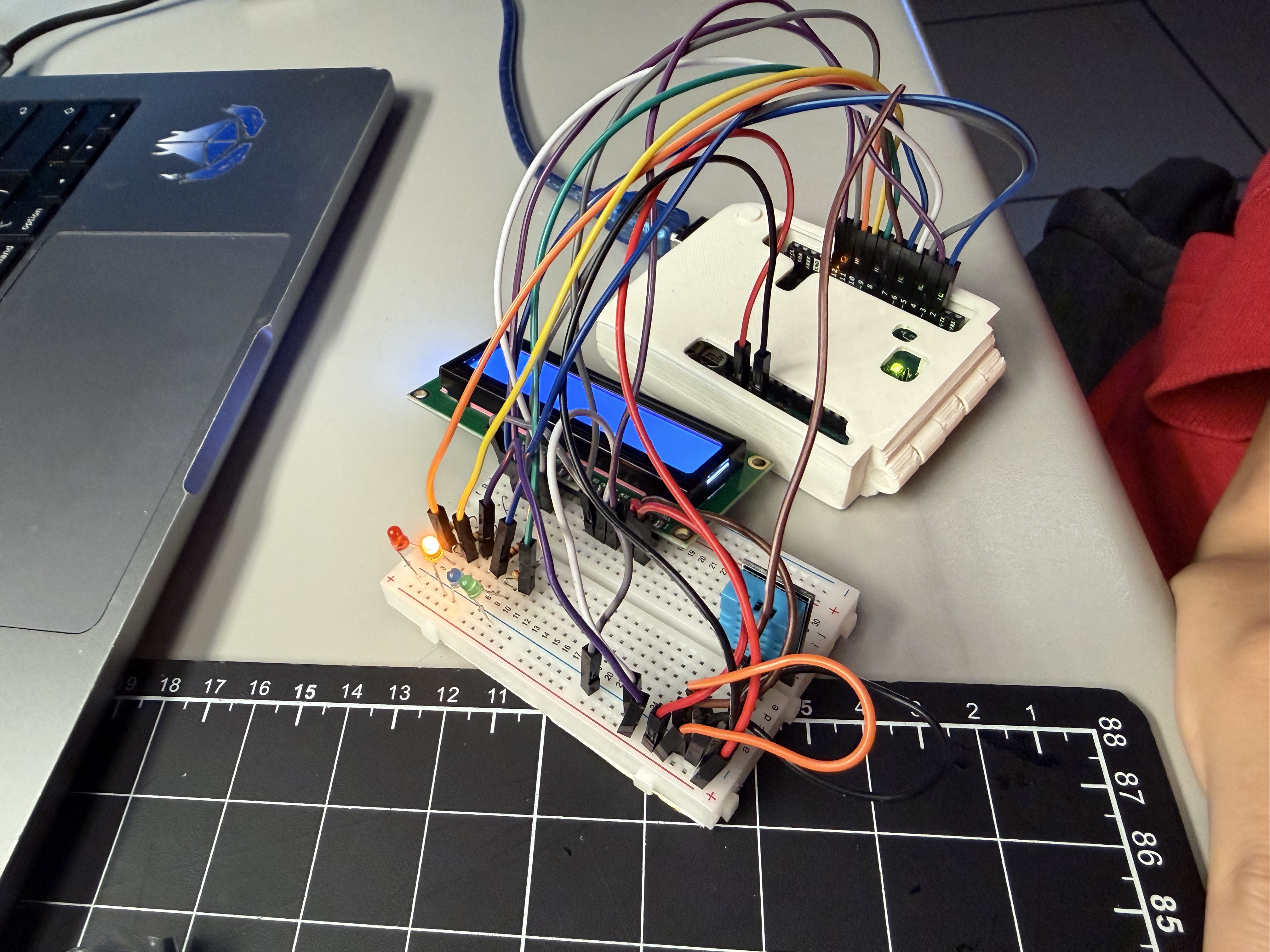
Activity 2: Iterating on DHT11 Data to LED Signals

Step 1 — Board selection and sensor choice: confirming the DHT11-based plan for data acquisition.
         DMX is too complex for now; focus on T/H first. using an Arduino Uno to connect to the DHT11 module for leds and serial output. Step 2 — Breadboard layout: DHT11 wired to the board; bench setup for serial testing. Step 3 — Wiring refinement: DATA, VCC, GND verified; ready for repeated sampling. Step 4 — Arduino sketch with tiers and hysteresis: BLUE/GREEN/YELL/RED thresholds and 1–2 s polling in the loop. Step 5 — End-to-end serial test: live T/H readings and stable red tier output; ready for UI integration next.

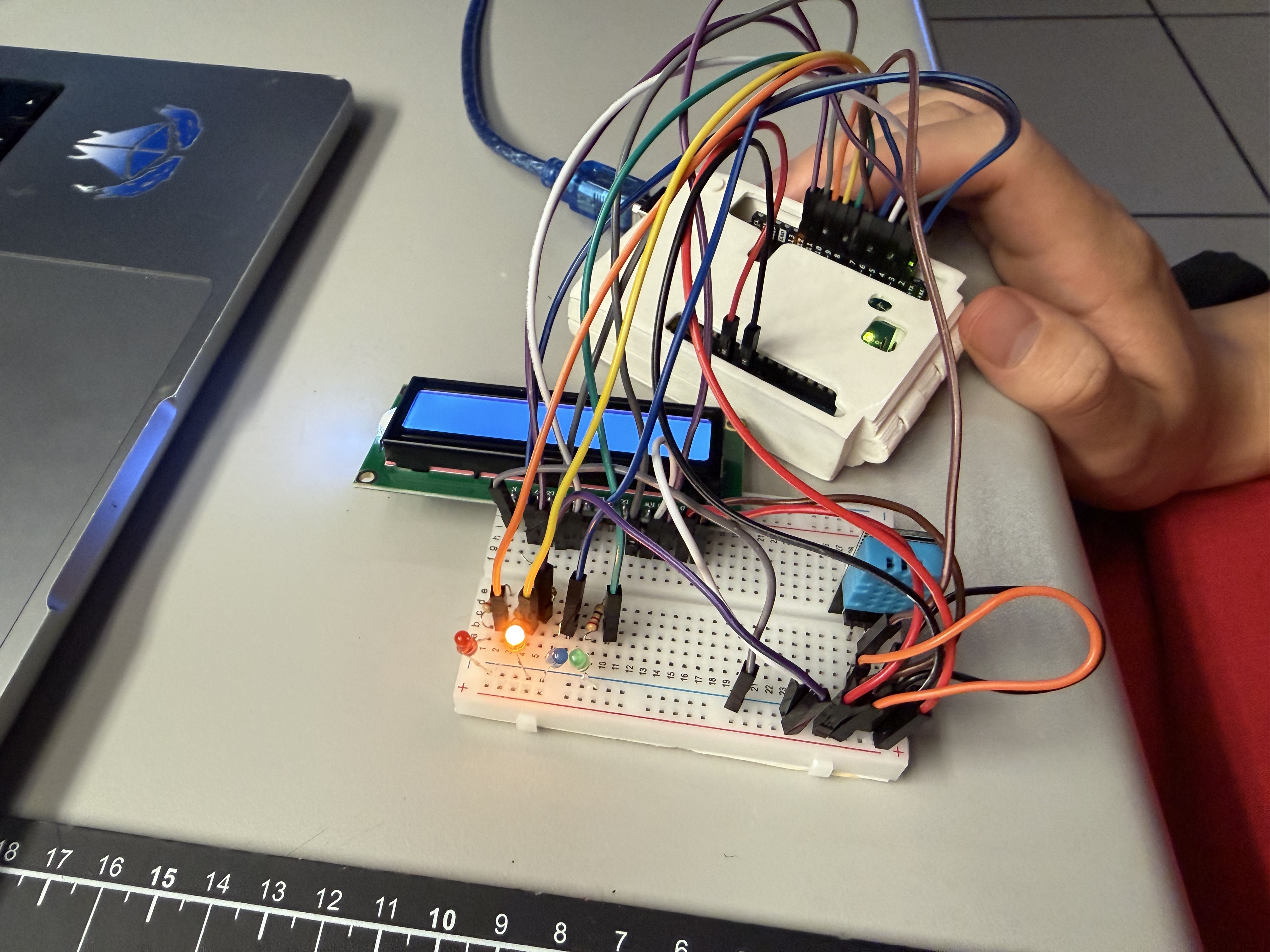
Action Research — Activity 3: Iterating DHT11 Data → LED Cues → LCD1602 Display

Step 1 — Arduino sketch prepared: DHT read, tier computation, LED control, and LCD print routine. Step 2 — Wiring the full stack: DHT11, LEDs with resistors, LCD1602 in 4-bit mode. Step 3 — Breadboard refinement: jumpers labeled; POT added for LCD contrast; stable 5V rails. Step 4 — LED cues live: tier changes drive blue/green/yellow/red LEDs; readings match expectations. Step 5 — LCD1602 readout: temperature, humidity, and tier label displayed and synchronized with LEDs.

Project 2


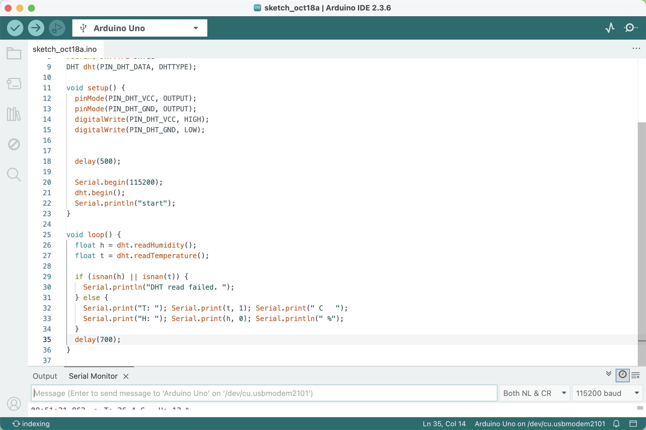
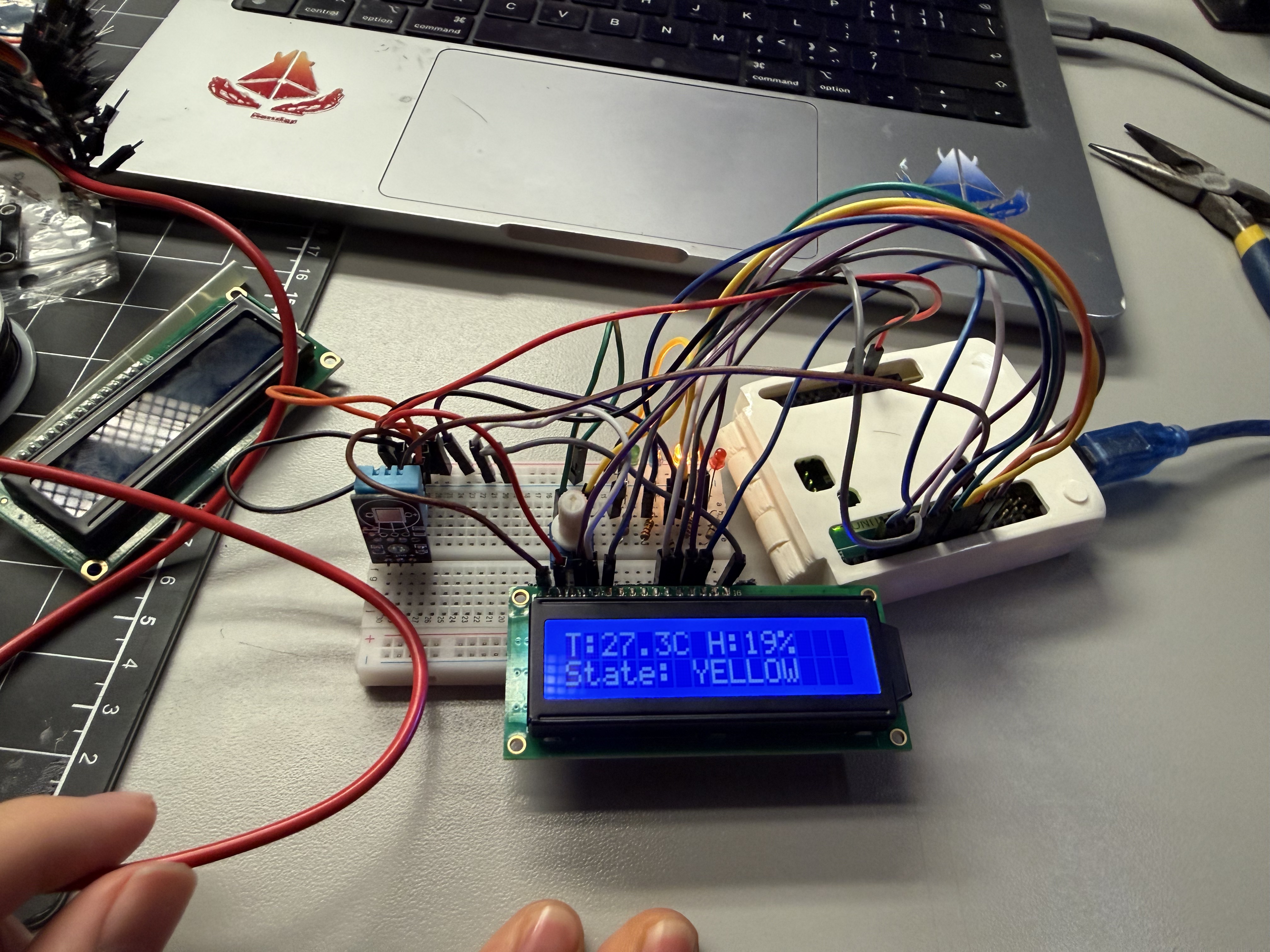
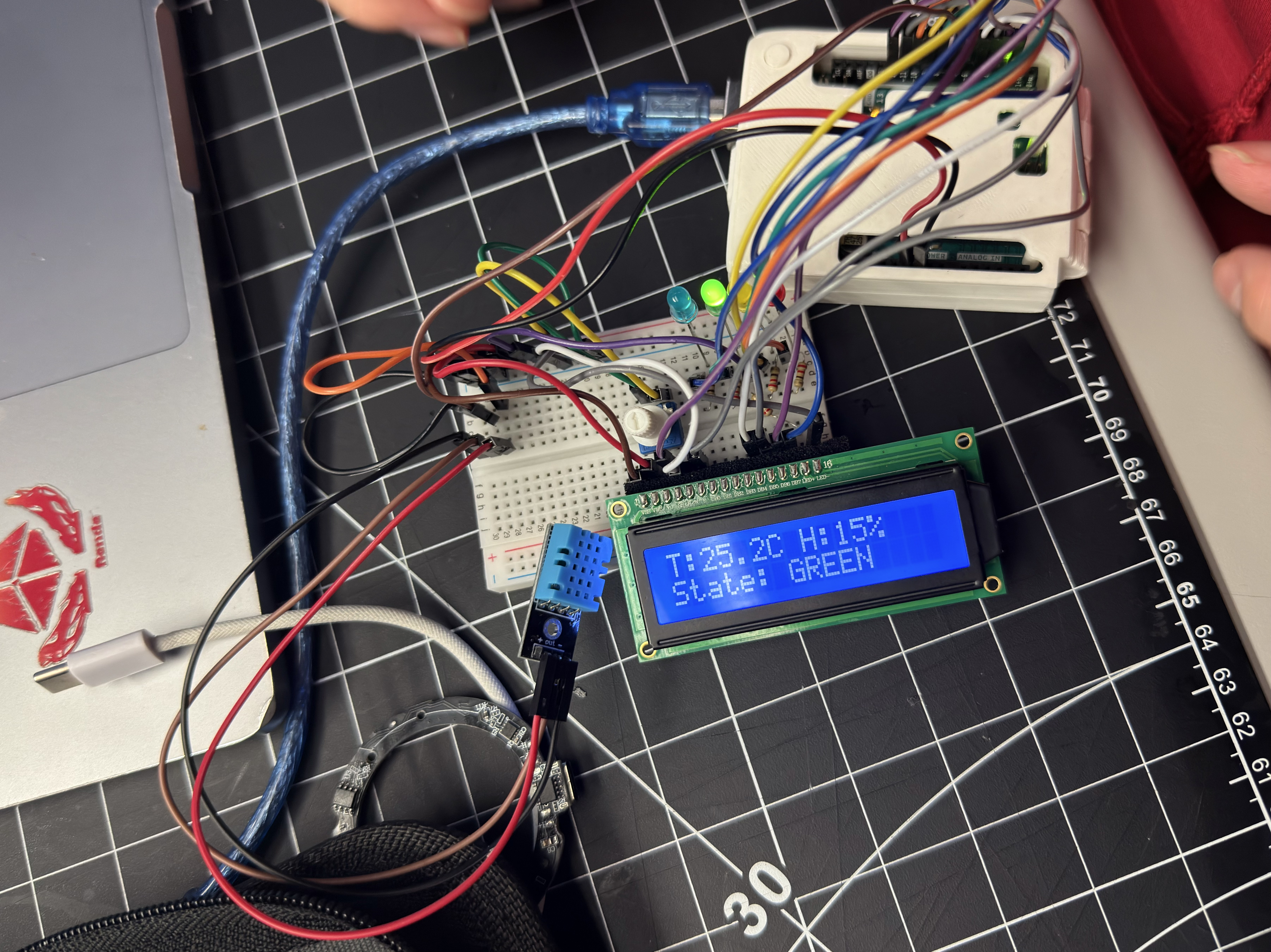
Project 2 Prototype — Comfort Lamp (Arduino + DHT + LCD)

I built a temperature–humidity “comfort lamp” that reads a DHT sensor and maps the result to four tiers with hysteresis (BLUE < 16°C, GREEN 16–26°C, YELLOW 27–34°C, RED ≥ 35°C). The LCD shows live T/H and the current state, while the RGB status light gives immediate ambient feedback. The system already streams clean serial messages for a ProtoPie bridge, so the next step is removing the LCD and shifting UI + audio to ProtoPie, plus adding a mode button, a pattern button, and a brightness/speed knob to increase physical interaction based on peer feedback.

Comfort Lamp v1 prototype: Arduino with DHT sensor, LCD showing T/H and state GREEN
v1 hardware demo — live T/H readout and tiered color feedback.
×

Powered by w3.css