Module 3 Activity Research

Weekly Activity

Yiyang Zhang


Project 3


Module 3

For Project 3 I am evolving the comfort lamp into a finished ambient object. After a group discussion we realized the lamp needs a physical scene instead of exposed electronics, so this module focuses on researching and prototyping a 3D-printed housing that frames the light, hides the Arduino hardware, and supports future ProtoPie interactions. Activity 1 documents my first round of research and the initial enclosure prototype.
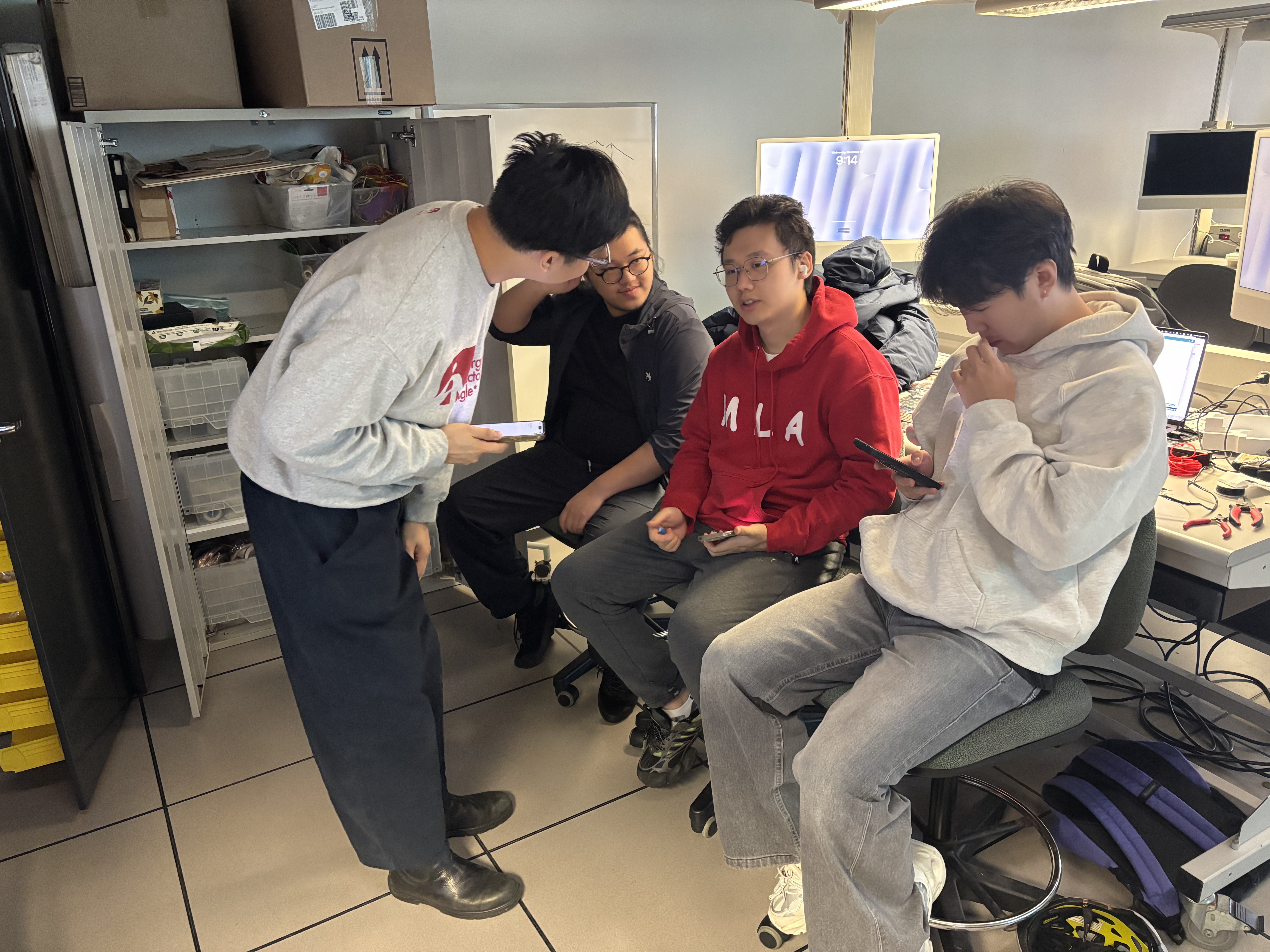
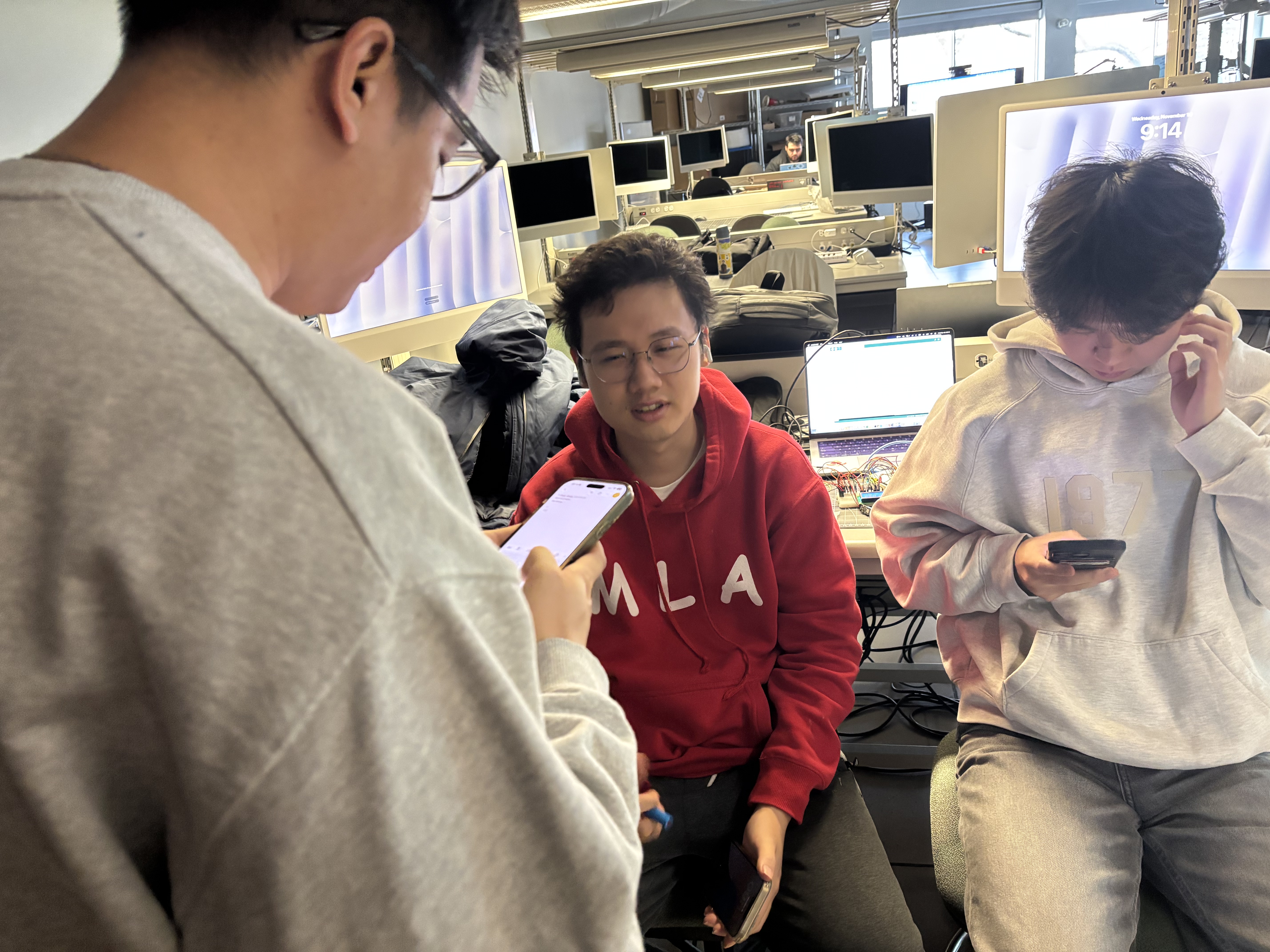
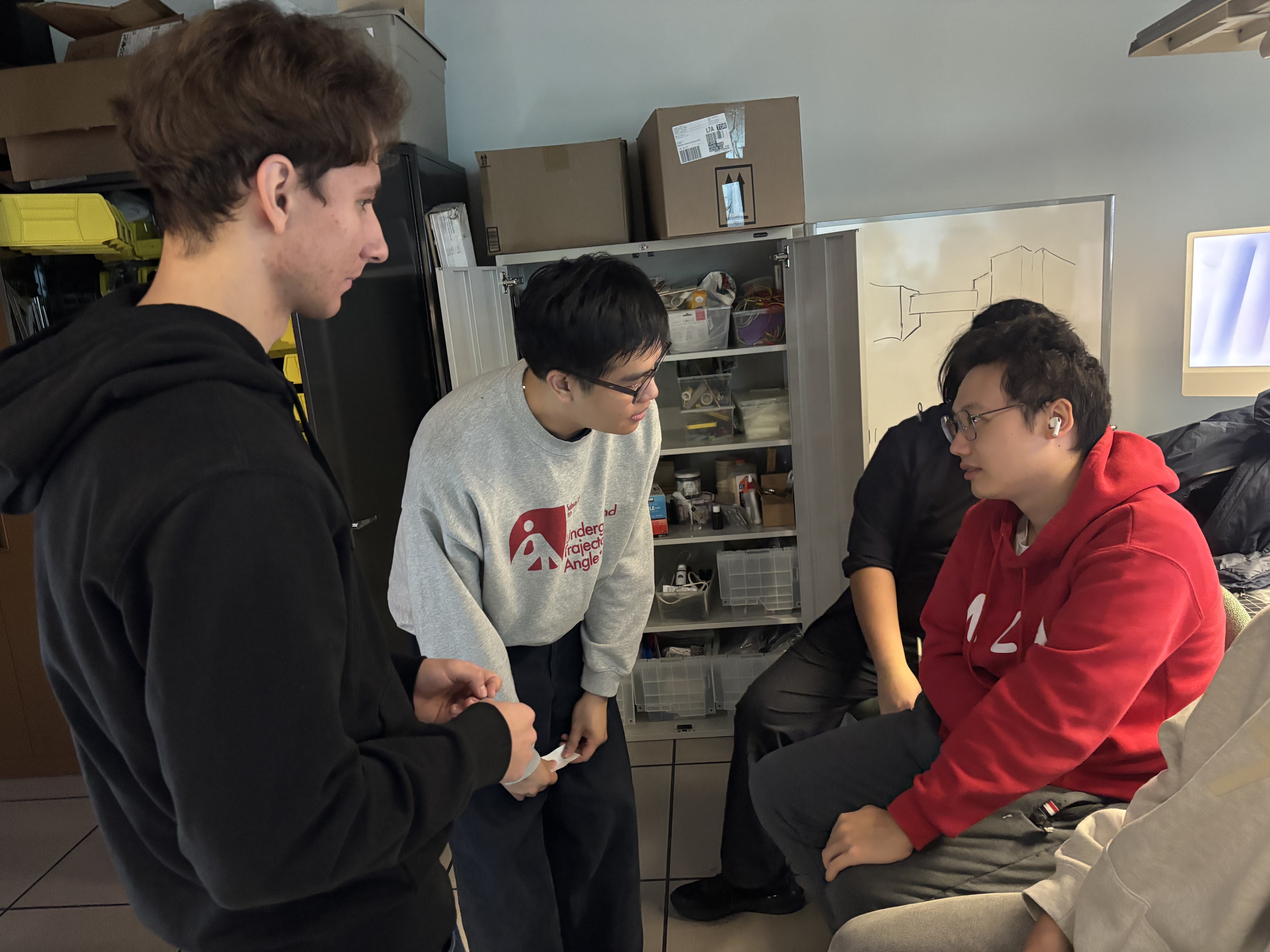

Workshop 1

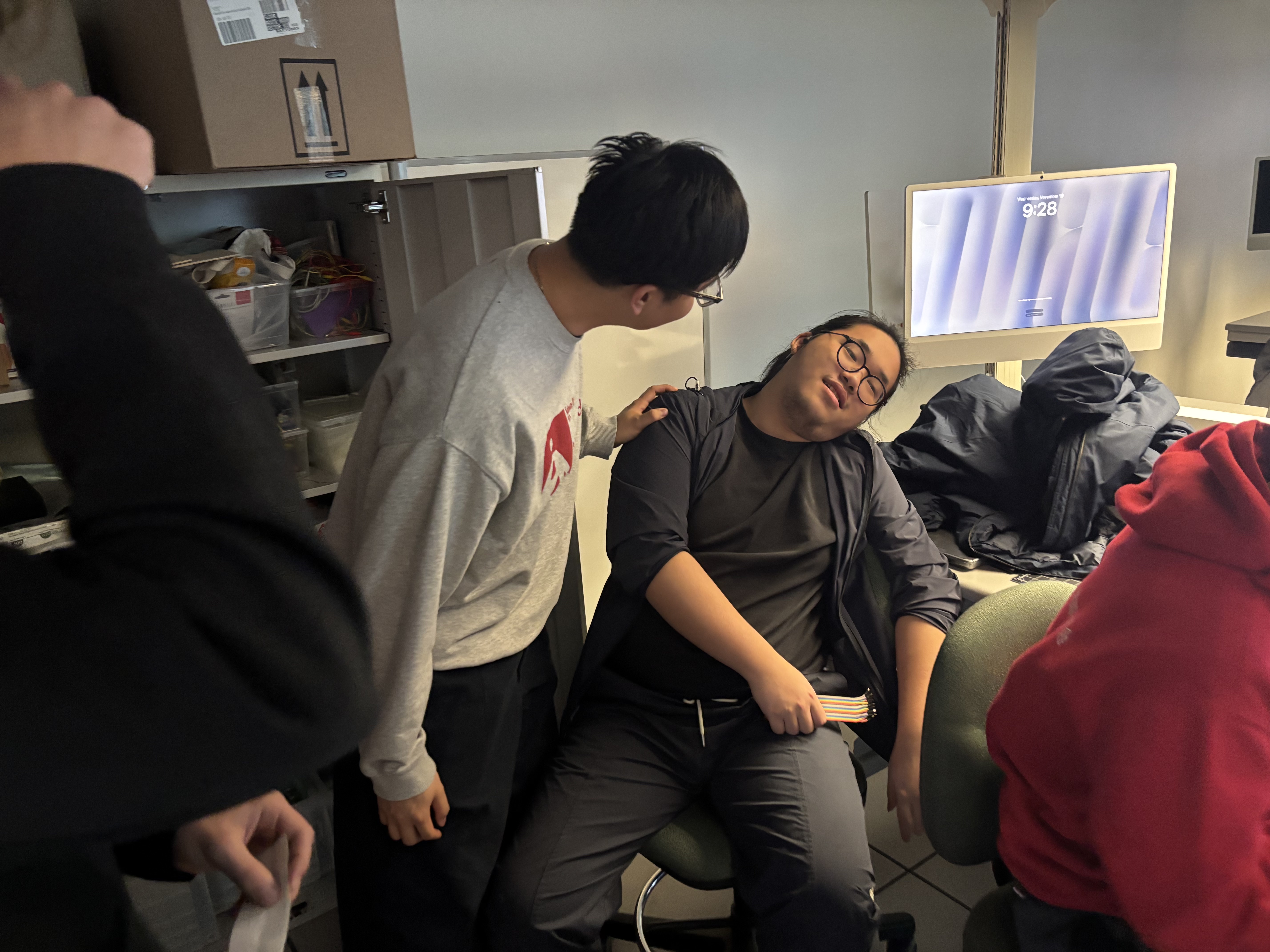
Workshop 1 was a bodystorming exercise where our team role-played a clinic visit to study doctor–patient communication. By acting as doctors, nurses, and patients, we tested how eye contact, body language, tone of voice, and digital tools (like using a phone for symptom checklists) affect trust and comfort. The photos document different scenarios from routine checkups to sudden “emergency” moments, helping us reflect on how interaction design can support clearer, calmer communication in real healthcare settings.
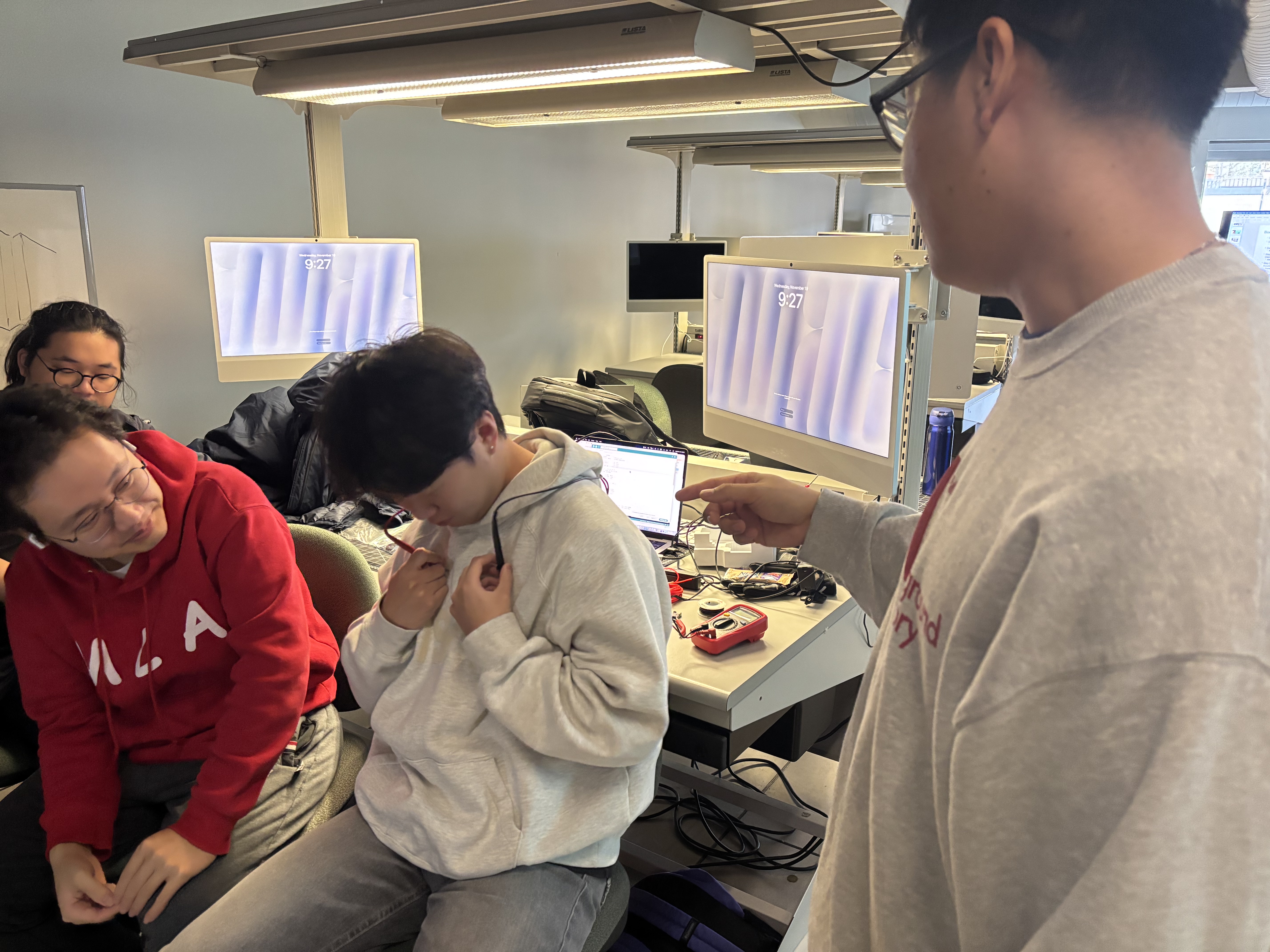
Our bodystorming challenge was to role-play a clinic visit. Minh and Valerii acted as nurses, Keegan played the doctor, and two of us, including me (Yiyang in the red hoodie), were the patients. This scene shows us setting up the consultation and explaining the exercise. Keegan, playing the doctor, reads questions from a symptom checklist on his phone while I sit beside the other patient. We used this moment to test whether a doctor can keep a friendly tone and explain things clearly even when they are focused on a digital tool. Here I am patient #2 in the red hoodie while Keegan leans in to talk directly to me about my symptoms. We were paying attention to eye contact, body language, and how comfortable it feels when the doctor gets close in order to listen carefully. In this scene another student plays a patient with chest pain, holding his hoodie near his heart while the doctor asks where it hurts. We used this role-play to see how simple questions and gestures can help the patient describe what they are feeling. The last photo shows a more dramatic case, where the patient pretends to faint in the chair and the doctor has to react quickly. This helped us think about how communication changes in an emergency and what kind of language still keeps the patient calm.

Workshop 2

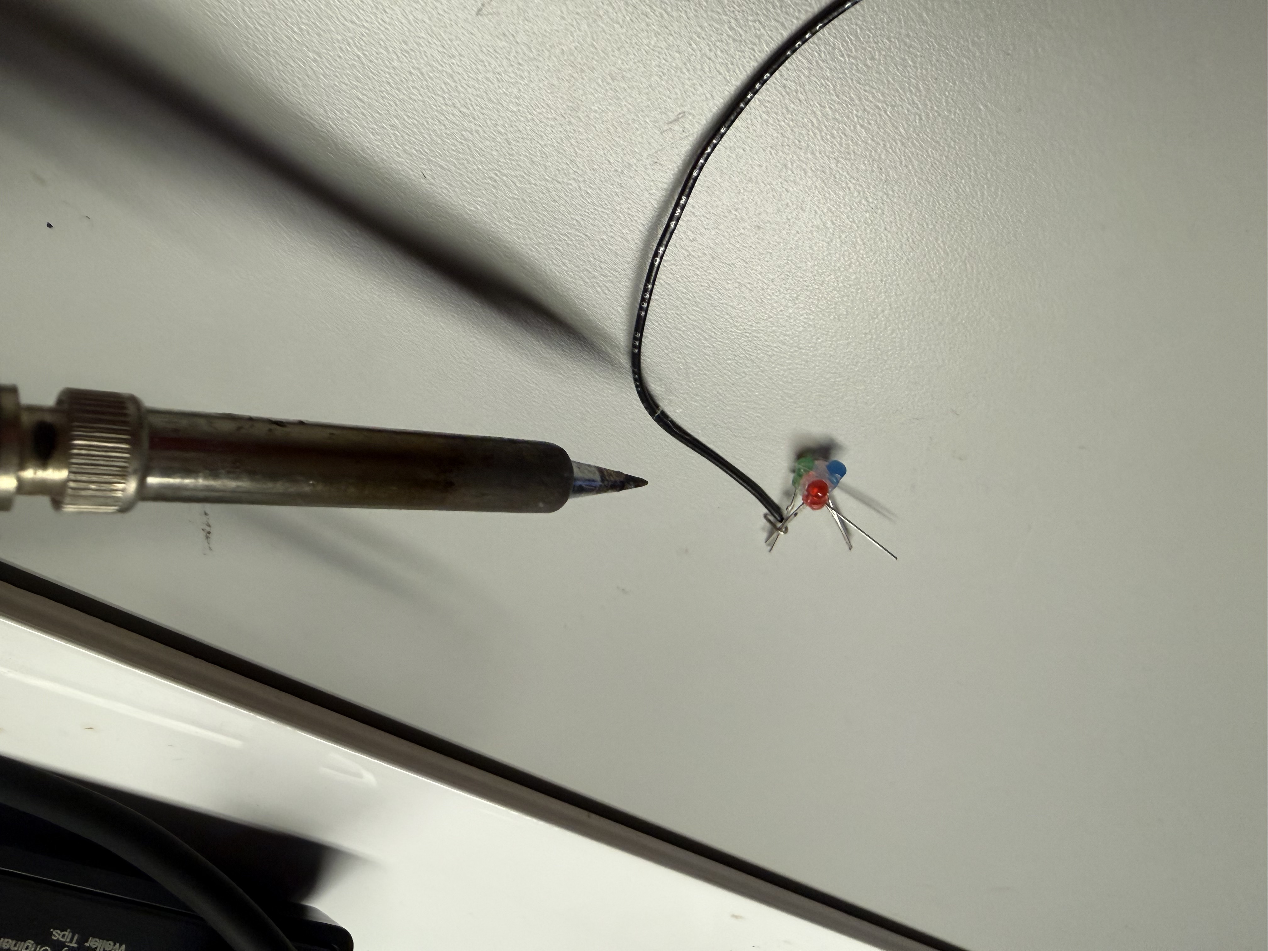
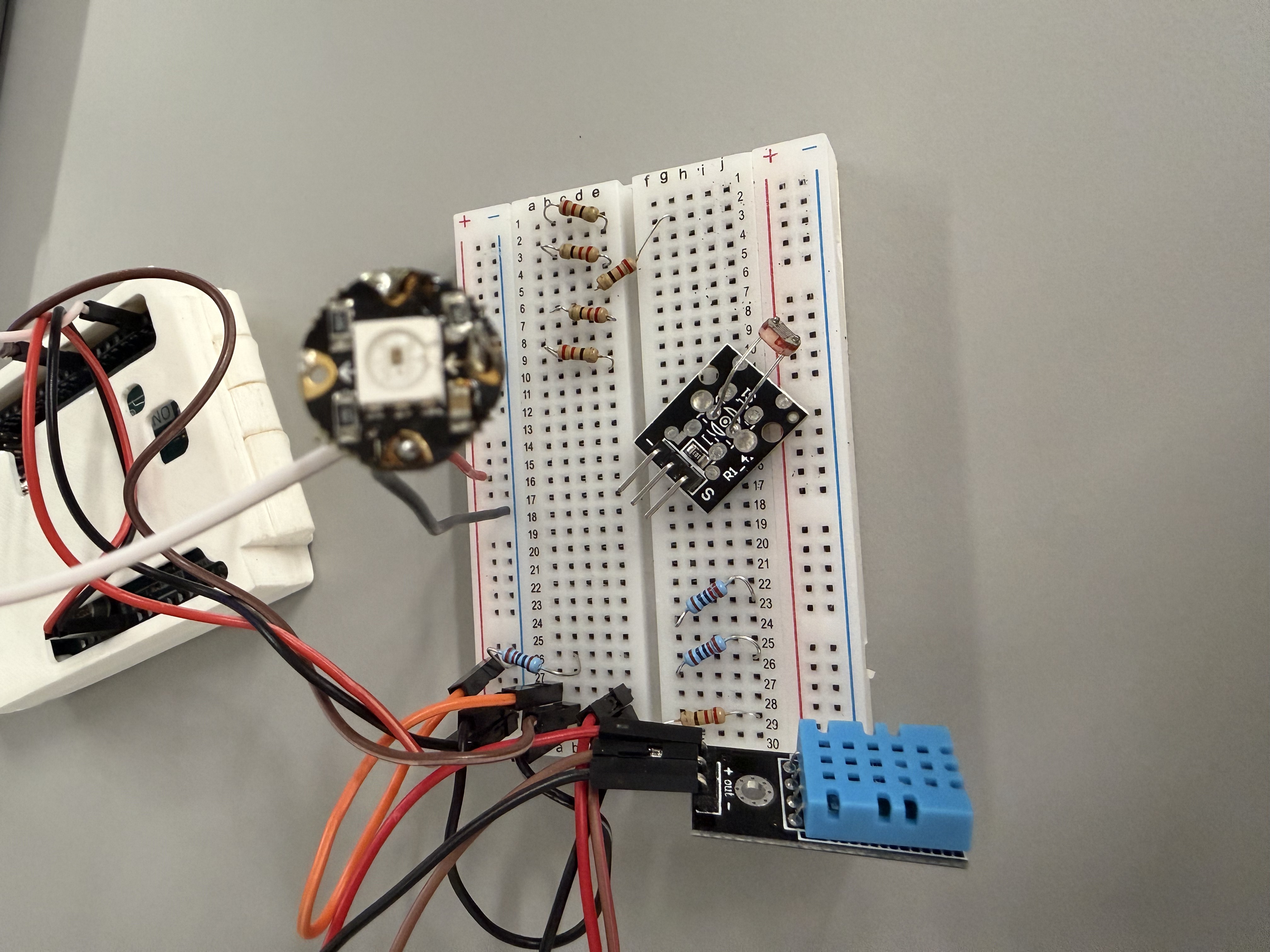
Workshop 2 focused on building and testing the electronics for my comfort lamp. I extended the LED wiring, created a reliable connector for the NeoPixel strip, and tested the full circuit on a breadboard with the Arduino, DHT sensor, and LCD. After confirming that the logic and tiered colors worked, I started placing the components into the new staircase-and-arches housing to study how the light behaves inside the scene.

Soldering longer wires to the LED with separate RGB leads, but discovering that the strip was not working properly. Finished wired connector to the NeoPixel strip, preparing a stable connection for the LED and sensor. Breadboard test of the comfort lamp logic: Arduino, DHT sensor, RGB LEDs and LCD all running to verify tier mapping and stability. First in-class test of placing the electronics into the new design scene, checking fit and the colour cycle. The lamp glowing in a warm tier inside the housing, evaluating how the staircase and arches catch and reflect the light.

Activity 1: Enclosure Design & Material Research

In Activity 1 I focused on the physical form of the comfort lamp. Based on our group discussion that an ambient lamp should live inside a scene, I researched architectural models, selected a staircase/arch design from Thingiverse, and modified it to fit the Arduino, DHT sensor, and RGB LEDs. The images below show the process from reference model to 3D print and first physical prototype.

Reference 3D model found on Thingiverse that I chose as the starting point for the ambient lamp scene. <a href='https://www.thingiverse.com/thing:7076687' target='_blank'>Thingiverse source link</a> My first modification of the original model in CAD, adjusting the interior architecture to create a stronger light scene for the comfort lamp. Second CAD iteration where I added clearance and a slot for the Arduino board, plus space for wiring and the DHT sensor at the back of the lamp. 3D printing in progress on the Ultimaker; this test checks wall thickness, overhangs, and print time for the modified lamp enclosure. Finished first physical prototype of the 3D-printed housing, ready for installing the comfort lamp electronics and testing how the light behaves inside the scene.

Activity 2: Electronics & Lighting Integration Tests

In Activity 2 I focused on testing the electronics inside the new 3D-printed housing. I soldered and extended the RGB LED ring, verified the comfort-lamp logic on the breadboard, then installed everything into the architectural scene to check brightness, colour tiers, and how the light behaves in the final enclosure.

Testing the RGB LED ring on its own, checking if it can adapt (at end it can not adapt my pipeline with arduino). Adjusting the position of the LED ring while the lamp is on to see how different placements change the light gradient in the scene.(plus color cycle) Cool/green tier test, checking if the colour still reads clearly once it is diffused by the 3D-printed structure. Warm/orange tier test, used to represent a less comfortable environment; verifying contrast against the other tiers. Bright magenta tier test, exploring a more intense alert state and how dramatic colours feel in the final ambient object.

Additional Research 1

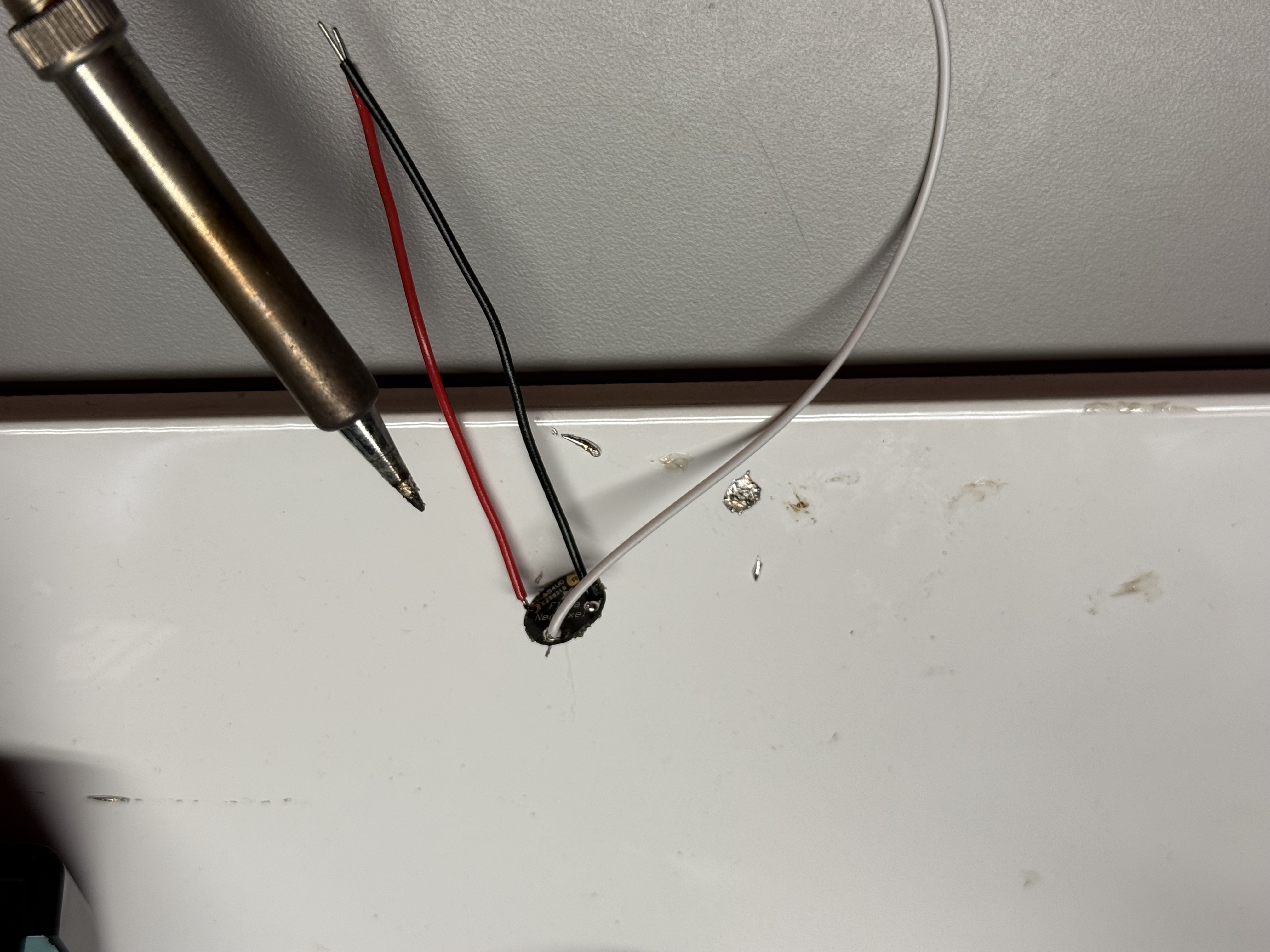
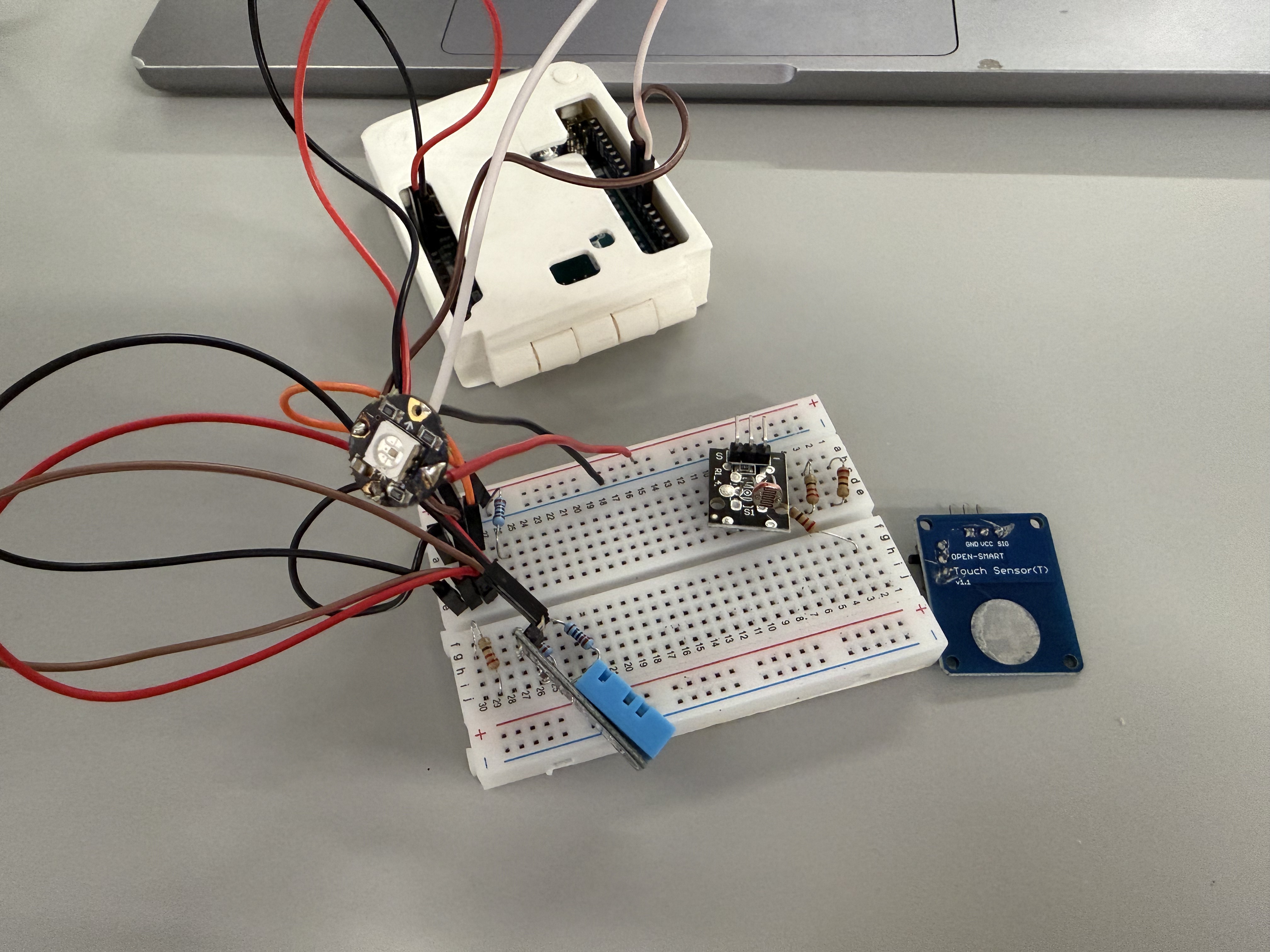
For this additional research I explored alternative sensing and interaction options for the comfort lamp. I removed the LCD module to simplify the circuit, added a light sensor so the lamp can react to ambient brightness, and tested a latching touch switch after our team discussion that “a lamp should always have a clear on/off control.” I then cleaned up the wiring, updated the code, and verified that the full system runs reliably with the new sensors and switch.

Breadboard prototype without the LCD screen, showing the DHT sensor, RGB LED and a new light-dependent resistor to measure ambient brightness. Second breadboard setup adding a latching touch switch, based on teammate feedback that the comfort lamp should have a clear on–off control. Rewired and tidied breadboard circuit with all components connected and the RGB LED successfully lighting up. Arduino IDE screenshot showing the updated code that reads the sensors and handles the latching touch switch logic. Live test of the prototype: the RGB LED responds while the latching touch switch and sensors are being triggered on the breadboard.

Additional Research 2

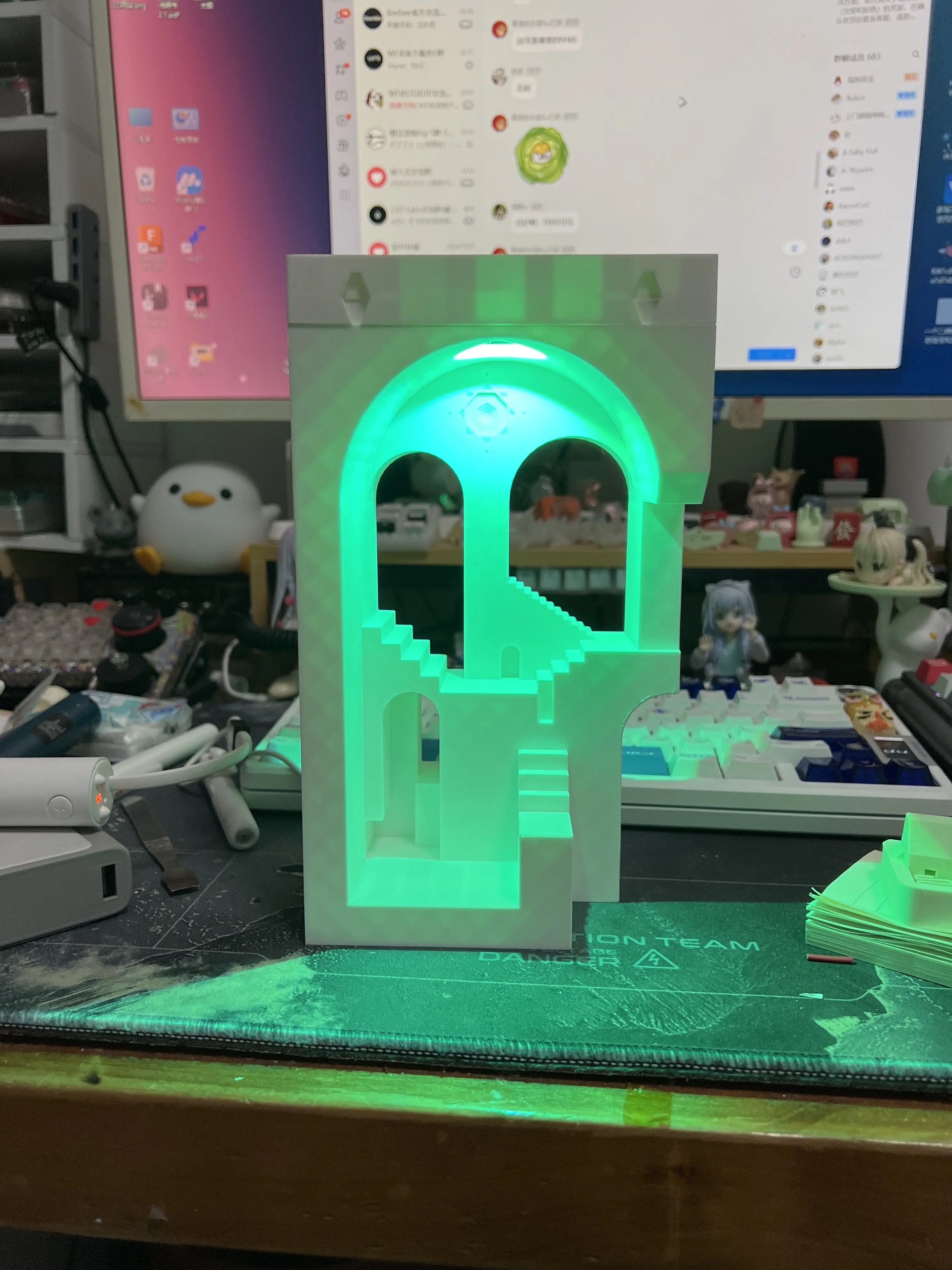
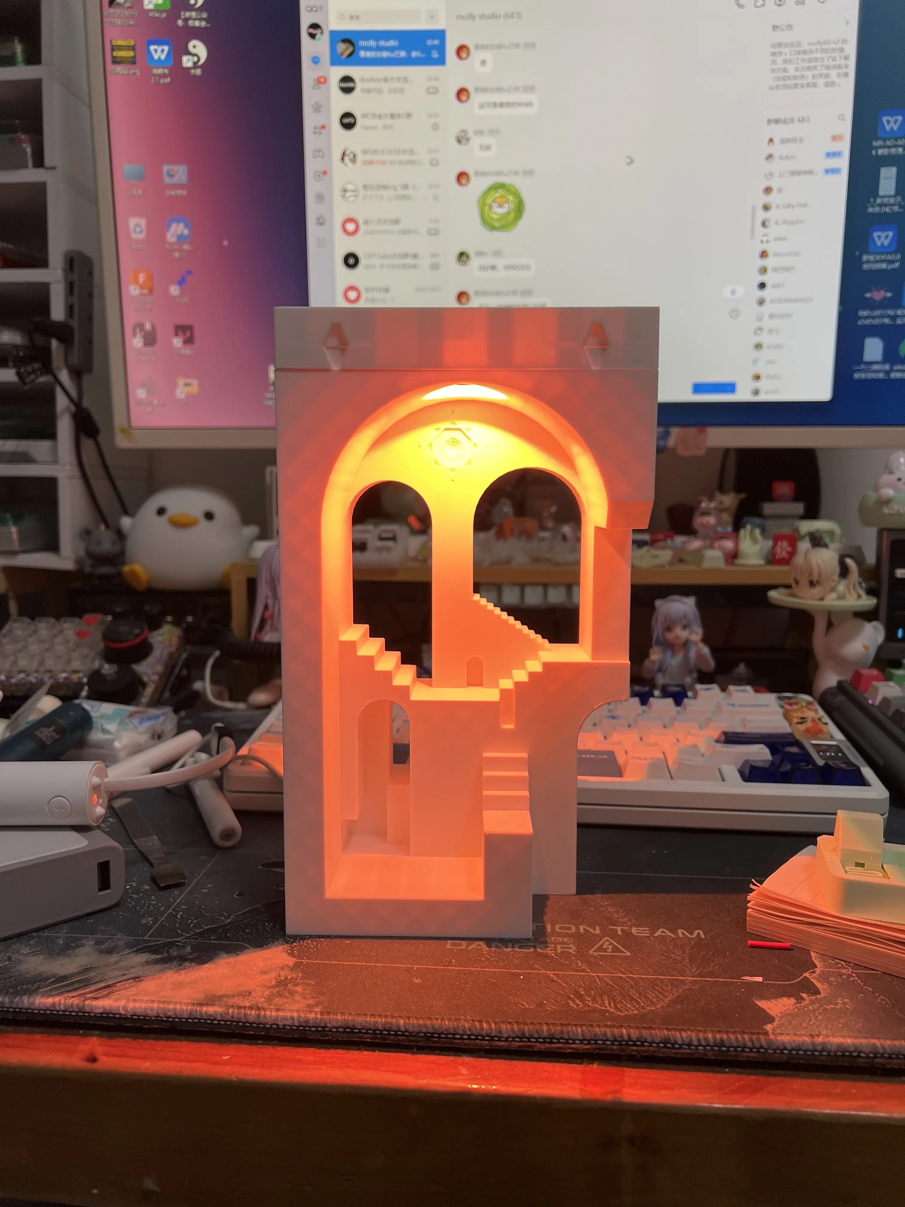
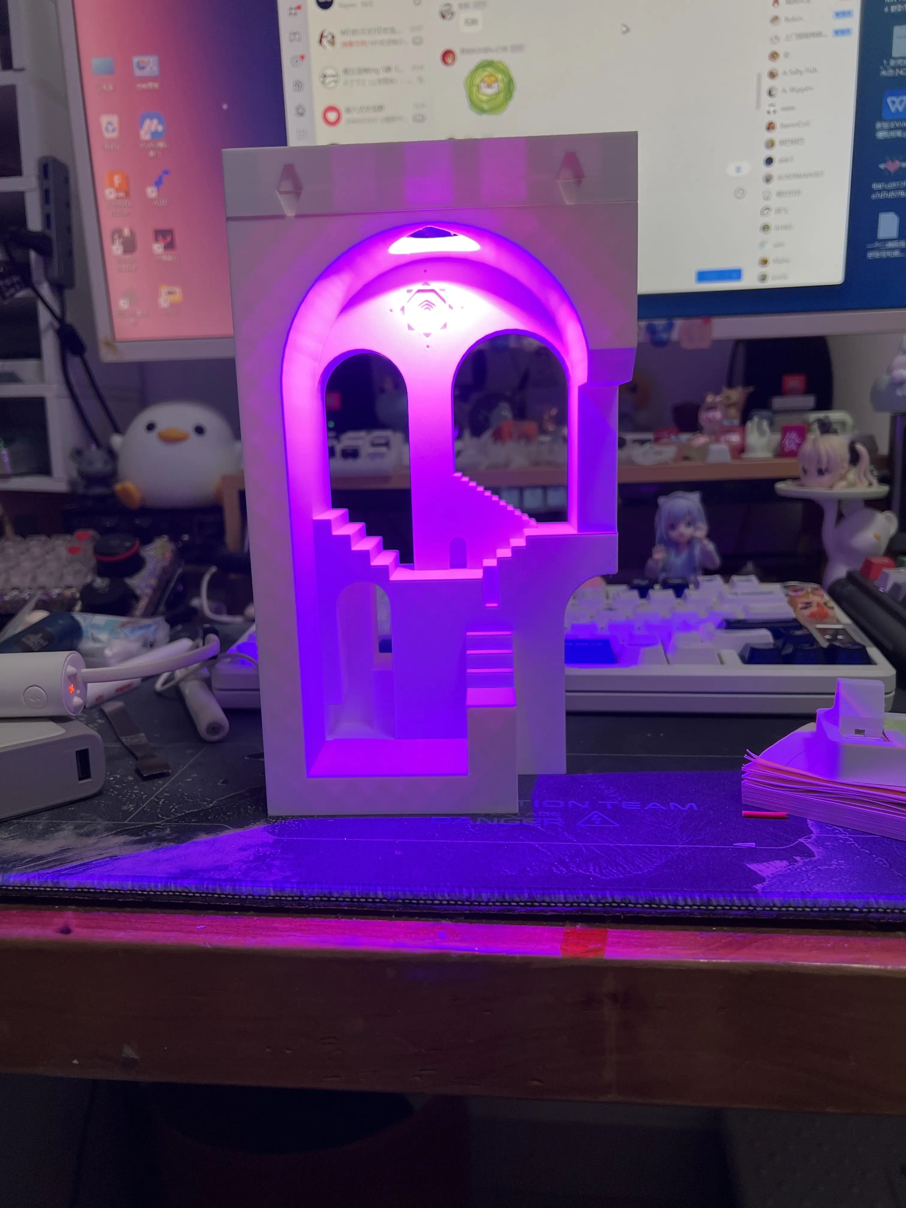
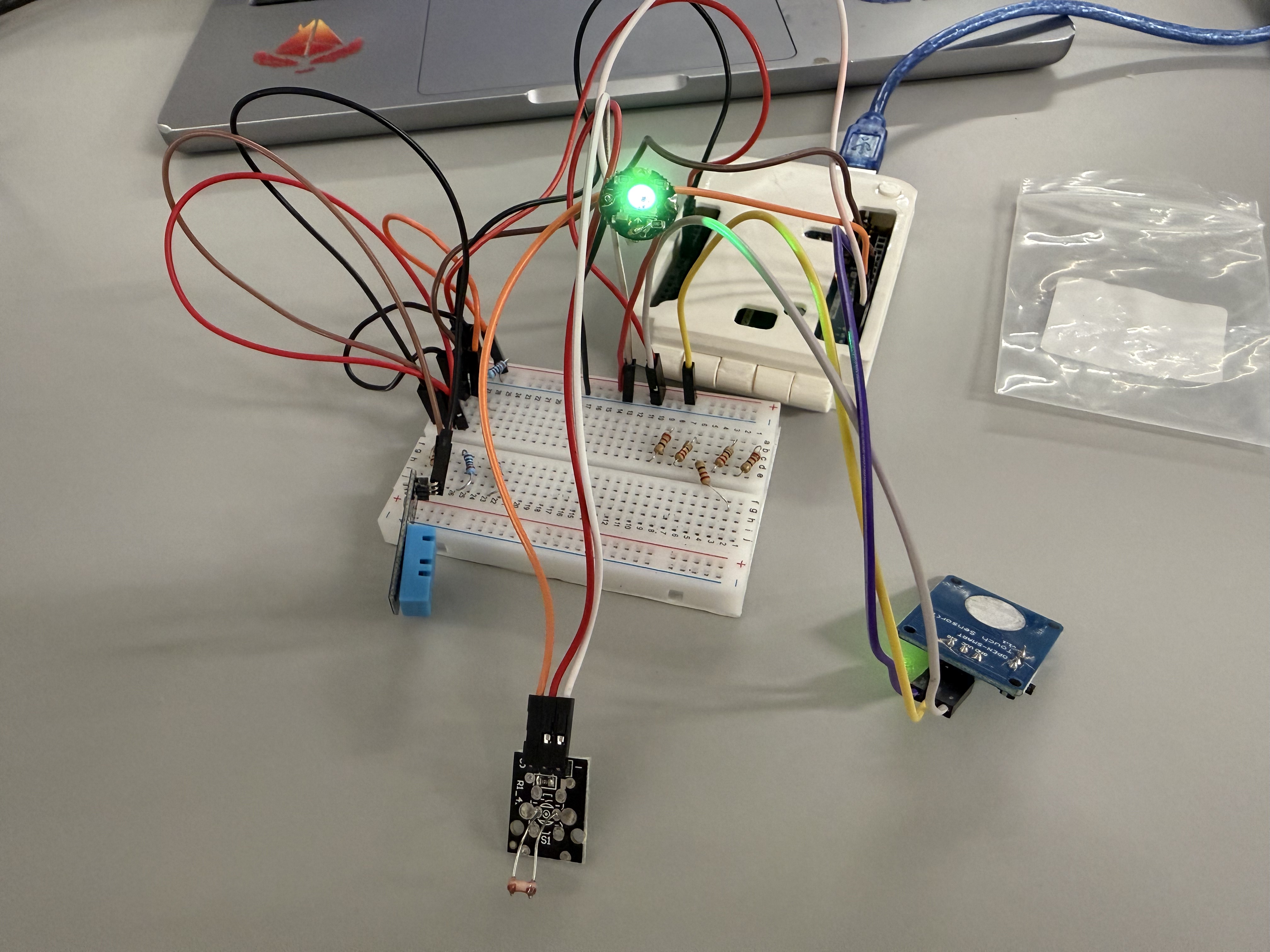
In this second round of additional research I focused on how the full comfort-lamp circuit fits and behaves around the 3D-printed enclosure. I first tested the latching touch switch and sensors on the breadboard, then brought the housing into the setup to check cable length, mounting positions and light spill. Finally, I ran a series of colour-tier tests (cool, neutral and hot states) with the enclosure in place to see how the LEDs wash across the stairs and arches and to confirm that the physical scene still makes the state changes easy to read.

Animated test of the full breadboard circuit with the latching touch switch and sensors, verifying that the comfort-lamp logic responds correctly when the switch is tapped. Checking the empty staircase-and-arch enclosure by hand to plan how the electronics will sit inside the 3D-printed volume. Breadboard, sensors and wiring arranged beside the 3D-printed enclosure, testing cable reach and layout before final assembly. Animated test with the enclosure in place, showing the interior glowing while the external breadboard circuit drives the LEDs. Close-up of the lamp glowing in a red tier inside the enclosure while the external circuit is still accessible for adjustment.

Project 3


Project 3 Final Prototype

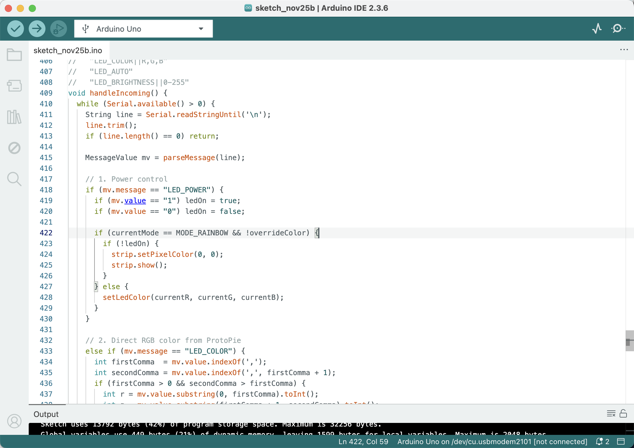
The final prototype turns my comfort lamp into a small architectural ambient scene. The 3D-printed staircase and arch are still driven by the tiered comfort-lamp logic, while temperature, humidity, and light level are read by sensors mounted on the side. A latching touch switch gives the lamp a clear physical on/off control, and my teammate’s ProtoPie mobile UI now connects to the Arduino to show the live sensor data and modes that used to be on the LCD, as well as send commands back to the lamp. The finished object works together with the phone interface: the phone handles detailed information and controls, while the lamp itself communicates through colour and glow as a calm atmospheric display.

Final prototype: a small architectural staircase and archway model lit from inside with a soft green LED glow, with the microcontroller and wiring attached on the side. Animated view of the final prototype cycling through rainbow and tiered colours to show different comfort states.
×

Powered by w3.css